As I described previously, this is just a 24v PWM. And I knew that people were going to want these but they were going to be too difficult for the common hobbyist to do on their own. I offered to make these at cost for club members. So I started to research prices of everything that I needed. Which was going to be around $15
Through some more research I found that there was already a PWM that could be picked up through ebay for $5.50 with free shipping.
Link provided here. Not only does these have great potential, the plugs work with the jebao driver. Win win right? Not quite. This 5-24v PWM will drop the output voltage lower than what the jebao driver uses, which can damage the circuits and possibly corrupt its programming. BTW, I’m not aware of a reset process for the drivers.
Jebao driver uses a linier voltage regulator to take a portion of the 24v input and convert it to 5v to power the circuit components. And the good thing about linier vr’s is that they are capable of working in a range of input voltages and still maintains a steady 5v output. Which is why these dimmers (when used in the proper range) aren’t going to cause problems to the driver. The downside to linier vr’s is that they can’t output 5v if the input voltage is less than 5v.
These led dimmers drop the output voltage below 5v. The easiest way to do this is to not allow the dimmer to drop below that 5v threshold. And I did that by simply changing the range in which the potentiometer (control knob) worked. A pot is just a variable resistor which changes the resistant value by a turn of the knob. All you have to do is add a resistor in series of the wiper terminal.
This process is fairly simple. I took lots of pics (some are not focused and for that I apologize)
Here we go:
Getting into the case isn’t tough, just remove the 2 screws and pull everything apart like so:


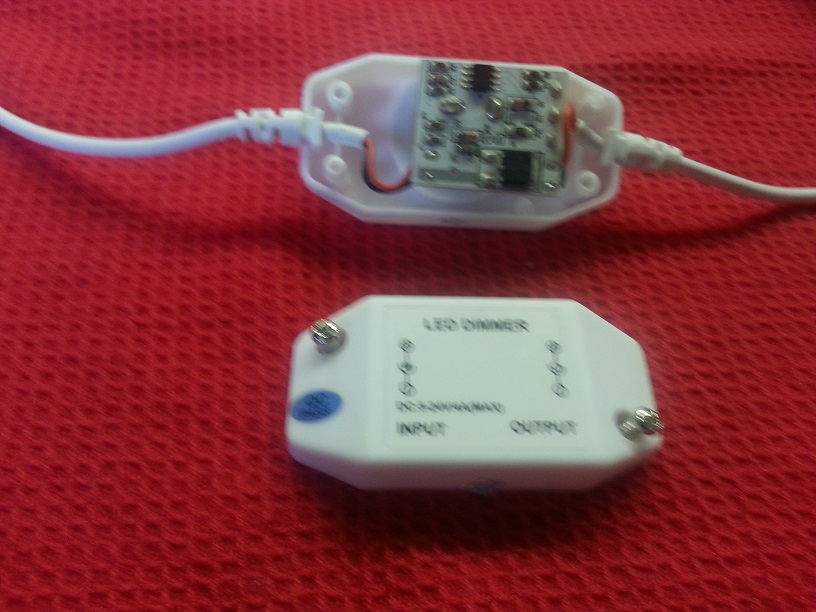
Use a flat head screw driver and pry the know knob off:
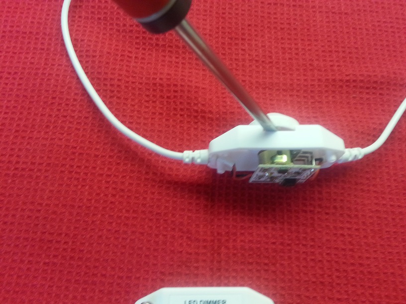
Remove the nut:


Now comes the fun part, using side cutters, cut the center terminal of the pot:
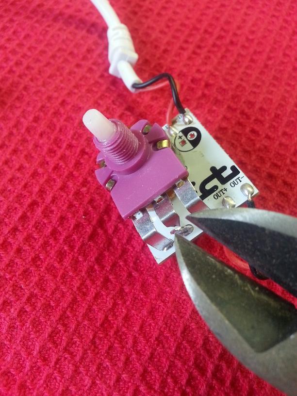
Remove the remaining part of the terminal that is still attached to the board. For this you are going to have to use a soldering iron:


This step is optional, I used this de-solder to remove the excess solder from the hole, making it easier to add the resistor later:


You can see how the hole is exposed ready to accept a resistor:

Drop a 1M Ω (1000K Ω) ¼ watt resistor which you can pick up at any radioshack. Direction of the resistor doesn’t matter:
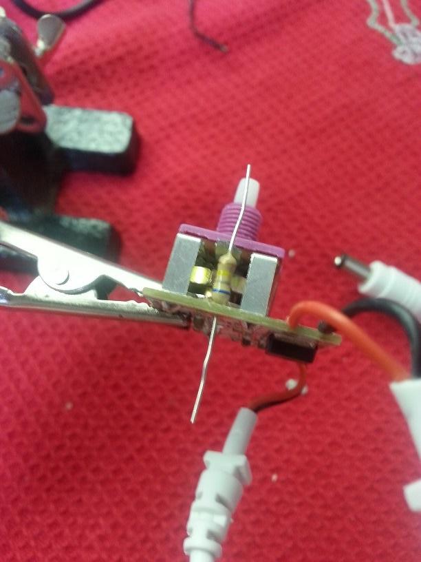
Now just solder the resistor in where you made the opening and trim the excess:

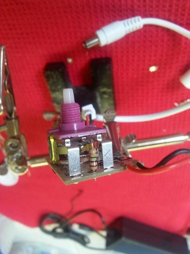
Put it all back together and plug everything in and now you have a PWM that will work with the jebao driver.

Now if this is still out of your comfort zone you can choose not to add the resistor and keep in mind not to turn the knob below the 5v threshold.
Also I want to add this disclaimer. Given that these are only $5 components and jebao’s are fairly cheap as well, it leads me to speculate that there isn’t too much quality control and it’s quite possible that every driver may be effected in different ways as well as every dimmer may have different variations and values within the outputs. Keeping that in mind attempt this at your own risk.


